| |
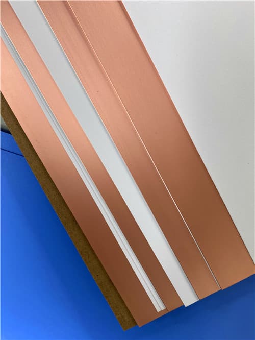
Wangling F4BME233 DK2.33 Df0.0011 (0.1-12.0mm) RTF Copper Clad Laminate
Brief Introduction
Wangling F4BME series are PTFE glass fabric copper-clad laminates that share the same dielectric layer as the F4BM series but utilize Reverse Treated Foil (RTF) copper. This configuration delivers excellent Passive Intermodulation (PIM) performance, more precise circuit control, and lower conductor loss, making it ideal for applications with stringent PIM requirements. F4BME233 is the variant with a dielectric constant of 2.33.
Technical Features & Benefits
- Selectable Dielectric Constant (Dk) from 2.17 to 3.0; customizable Dk available.
- Low dissipation factor (low loss).
- Excellent PIM performance (≤ -159 dBc) due to Reverse Treated Foil (RTF) copper.
- More precise line control and lower conductor loss.
- Good dimensional stability and enhanced size control.
- Radiation resistance and low outgassing.
- Commercial, high-volume, cost-effective production.
- UL 94 V-0 flammability rating.
.jpg)
Typical Properties: F4BME 233
| Properties |
Test Conditions |
Unit |
F4BME233 |
| Electrical Properties | | | |
| Dielectric Constant (Typical) | 10 GHz | - | 2.33 |
| Dielectric Constant Tolerance | / | - | ±0.04 |
| Dissipation Factor (Typical) | 10 GHz | - | 0.0011 |
| 20 GHz | - | 0.0015 |
| Temperature Coefficient of Dk | -55°C to 150°C | ppm/°C | -130 |
| Peel Strength | 1 oz. F4BME | N/mm | >1.6 |
| Volume Resistivity | Normal Condition | MΩ·cm | ≥6×10⁶ |
| Surface Resistance | Normal Condition | MΩ | ≥1×10⁶ |
| Dielectric Strength (Z-direction) | 5 kW, 500 V/s | kV/mm | >23 |
| Breakdown Voltage (XY-direction) | 5 kW, 500 V/s | kV | >32 |
| PIM Performance | Only for F4BME series | dBc | ≤ -159 |
| Thermal & Mechanical Properties | | | |
| CTE | XY-direction, -55°C to 288°C | ppm/°C | 22~30 |
| Z-direction, -55°C to 288°C | ppm/°C | 205 |
| Thermal Stress | 260°C, 10s, 3 cycles | - | No Delamination |
| Water Absorption | 20±2°C, 24 hours | % | ≤0.08 |
| Density | Room Temperature | g/cm³ | 2.20 |
| Long-term Operating Temperature | High/Low Temp Chamber | °C | -55 to +260 |
| Thermal Conductivity | Z-direction | W/(m·K) | 0.28 |
| Flammability Rating | / | UL-94 | V-0 |
| Material Composition | / | / | PTFE, Glass Fiber Cloth; F4BME uses Reverse Treated Foil (RTF) copper. |
Application Areas
- Microwave, RF, Radar
- Phase Shifters, Passive Components
- Power Dividers, Couplers, Combiners
- Feed Networks, Phased Array Antennas
- Satellite Communication, Base Station Antennas
- Applications requiring excellent PIM performance.
Available Configurations
- Copper Foil Options for F4BME: Reverse Treated Foil (RTF) Copper. Available thicknesses: 0.5 oz (0.018mm), 1 oz (0.035mm).
- Standard Panel Sizes Available: 460 × 610 mm, 500 × 600 mm, 850 × 1200 mm, 914 × 1220 mm, 1000 × 1200 mm
- Available Thicknesses & Tolerances (Conventional): Thickness (mm): 0.1 (core), 0.127 (core), 0.2, 0.25, 0.5, 0.508, 0.762, 0.8, 1.0, 1.5, 1.524, 1.575, 2.0, 2.5, 3.0, 4.0, 5.0, 6.0, 8.0, 10.0, 12.0. Corresponding tolerances range from ±0.01mm to ±0.20mm. Note: For Dk ≤ 2.65, minimum core thickness is 0.1mm. For Dk 2.7–3.0, minimum core thickness is 0.2mm.
- F4BME Series with Metal Core (Aluminum/Copper Base): Models: F4BME*-AL (Aluminum base), F4BME*-CU (Copper base). Serves for shielding or heat dissipation. Example: F4BME233-CU represents F4BME233 with a copper base. Standard sizes available: 460×610 mm, 460×305 mm. Other sizes upon request.
|
|
.jpg)
.jpg)
.jpg)
.jpg)
.png)
.jpg)
.jpg)